This post is going to be a bit incomplete because I haven't got all the pictures with me here, but I was bored, so I thought I'd start it off.
The problem with the Digifiz is that after paying all that hard-earned cash for one, you no longer have the correct km indicated in your car anymore. (For those who are fitting one into a RHD UK-spec car then the lack of mileage reading is a problem, too. But there's a solution for that later on.) Having determined how to reset the km on my own units and for a few other people, I decided to share the knowledge. This information is useless to you unless you have electronics experience and access to a suitable device programmer.
There are at least two major variations of the main board within the Digifiz that I am aware of. Only the newer variant may be reprogrammed. They can be identified as follows:
The newer version of PCB has an image of a rabbit etched in the copper foil, and it also has a sticker that says "DIGIFIZ REDESIGN". It is this newer version of board that can have its km recorder reprogrammed or reset. The board contains a small serial-access EEPROM in an eight-pin package of type NMC9307EN. It is this IC that contains the data for the km recorder and service intervals.
The older version of PCB has a larger number of ICs. Most noticeable is the fact that a large 40-pin IC sits in the space where the rabbit lives on the newer PCB. I think this large IC package contains the km data on this PCB but there's no datasheet available anywhere for this device. So we're a bit stuffed with that.
Someone has just sent to me a new version of PCB on which the sticker says "DIGIFIZ REDESIGN II"; I haven't had time to determine what's different about it yet, but fingers crossed the bloody thing can be reprogrammed! It has the NMC9307 on it, so hopefully.
I've got several of both types of board, so I will take some pictures eventually to show you the differences. And what the rabbit looks like.
This is a picture of the serial EEPROM on the board. It needs to be desoldered.
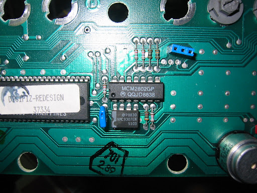
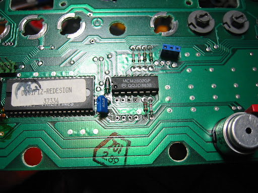
Out it comes. This is a double-sided PCB so it can be tricky to desolder. My method is to suspend the PCB vertically, then heat the IC pin on the component side of the board and use the sucker on the other side. If you have better desoldering gear then great (but I'm used to doing it the poverty way). In its place a socket will be fitted, allowing easy refitting and removal in the future (which is essential because doing the reprogramming stuff involves a lot of trial and error).
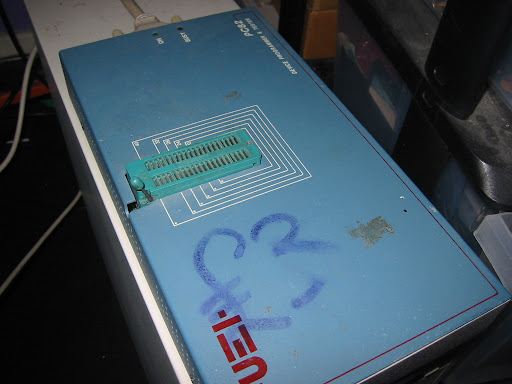
To reprogram the serial device you need to use an old-school device programmer like this that probably originally cost £500 in its day, but actually cost you £3 from an amateur radio rally when you were 17 (yes, alright, I got a girlfriend eventually). This is quite a powerful unit that can do all sorts of devices including our little serial EEPROM out of the Digifiz. Those cheap EPROM programmers you see on eBay will only be suitable for programming parallel EPROMs (the kind used in Digifant ECUs for instance) and will NOT program this device.
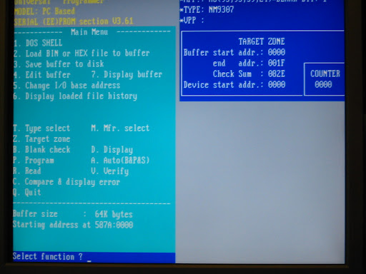
The massive thirty-two bytes in the EEPROM contain data that looks like this:
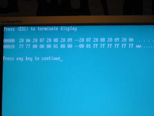
Look at the first pair of bytes. It represents the value 0x200A or 8202 decimal. Multiply it by eight. You get 65616. This is basically the km, but with the four least significant bits missing. The LSBs are contained in the two bytes that are 0x77 0x77 in that picture. Now you'll notice that there are actually eight pairs of bytes with very similar km values. Why? I'm not sure but the Digifiz seems to record its last km in a 'round robin' fashion across these eight values. When it next starts up, it picks out the highest one from those eight and displays that. Now those two bytes at the bottom left (77 77) contain the four LSBs for each of those eight km values.
In this case, the highest value, 0x200A, multiplied by eight added to 3 gives 65619:
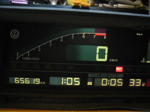
Ignore the fact that there's a main bulb missing. My bench PSU isn't man enough to light them both up.
So yeah, simply calculate the km you want, program it in and bingo.
Finally the next eight bytes on (after the 77 77) contain service interval data if I remember right (which you can reset on the Digifiz using the clock buttons anyway) and the 0xFF values towards the end are not used for anything.
Oh, one more thing.
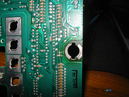
I think this is a bit of a design fault with the Digifiz. That bulb gets awfully hot (they all do) and on this board, that SMT resistor eventually just fell off. So if you get a totally dead Digifiz, see if that resistor is still there...
![]()


